

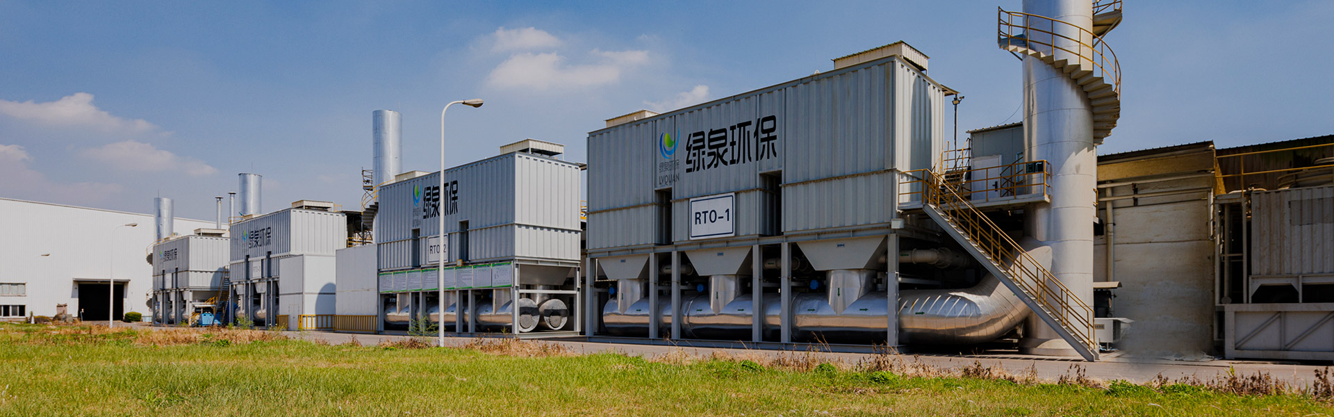
LQ-RTO 열 저장 고온 소각 장비
Cat:장비
타워 형 RTO의 개요 재생 열 산화제 (RTO)는 고온 산화와 다중 타워 열 저장 기술을 결합한 유기 폐기물 가스 처리 장비입니다. 효과적으로 열 손실을 줄이고 에너지를 절약합니다.
세부 사항을 참조하십시오
At our factory in Yangzhou, the core technologies we manufacture are catalytic combustion equipment , regenerative thermal oxidizers , zeolite rotary concentrators , activated carbon adsorption units, and condensation recovery systems. These pieces are combined into the complete engineering systems that ship to end customers.
The selection of an odor control system is driven by three numbers: the total air flow in cubic meters per hour, the inlet VOC concentration in mg/m³, and the destruction efficiency demanded by local regulations. In China, for example, the national emission standard for industrial VOCs in many provinces is 60 mg/m³ for total non-methane hydrocarbons, but some local standards go as low as 30 mg/m³. A system that achieves 95% destruction may pass one region and fail another.
Manufacturers and plant engineers also need to consider whether the exhaust contains sticky resins, particulate matter, or chlorinated compounds. These contaminants can poison catalysts, adsorbents, or heat exchangers if not removed through pre-treatment. A horizontal spray cabinet or gas heat exchanger as pre-treatment can be the difference between a system that runs for ten years and one that requires a replacement adsorbent every eight weeks.
Five families of technologies dominate the market. Each has a distinct working principle, cost structure, and application window. The table below summarizes the key technical distinctions that a plant engineer should use when screening vendors.
| Technology | Concentration Range | Destruction Efficiency | Best Fit Scenario |
|---|---|---|---|
| Activated carbon adsorption | Low, 100–1000 mg/m³ | 90–98% (saturated) | Solvent recovery, intermittent operation |
| Zeolite rotary concentrator | Low, 50–500 mg/m³ | Concentrates 5–15x | High air flow, low concentration exhaust |
| Catalytic oxidation (CO) | Medium, 1000–5000 mg/m³ | 95–99.9% | Continuous operation, no sulfur/chlorine |
| Regenerative thermal oxidation (RTO) | Medium to high, 1000–10000 mg/m³ | 97–99.5% | High concentration, continuous, no recovery |
| Condensation recovery | High, >10000 mg/m³ | 70–90% | Single solvent, high concentration, valuable product |
From the table, a plant with 20,000 m³/h of air at 200 mg/m³ would be a poor fit for a direct thermal oxidizer, which would burn a large amount of supplementary natural gas. A zeolite rotary concentrator followed by a catalytic oxidizer is far more economical because the concentrator raises the dilute stream to 2,000–3,000 mg/m³ in a much smaller flow, allowing the oxidizer to operate autothermally.
On the other hand, a stainless steel label printing shop with a 300°C hot air dryer might emit at 4,000 mg/m³ in only 3,000 m³/h. Here an RTO with a high-efficiency ceramic heat exchanger can operate with natural gas consumption close to zero after reaching steady state. The capital cost is higher than an activated carbon system, but the annual energy savings and the fact that no adsorbent replacement is needed make the total lifecycle cost lower.
A special consideration for manufacturers is whether the wastewater from a washing tower or the spent adsorbent from activated carbon units has to be disposed of as hazardous waste. In China, spent granular activated carbon from VOCs treatment is classified as hazardous waste and must be sent to licensed recycling facilities, which adds a cost of RMB 3,000–5,000 per ton. RTO systems, by contrast, produce no solid waste, only CO₂ and water.
The fundamental principle behind every odor control system is either capture or destruction . Adsorption, condensation, and absorption are capture methods: the VOC molecules are transferred into a solid or liquid phase, and the contaminants are not destroyed but recovered or later desorbed. Oxidation, whether catalytic or thermal, is a destruction method: the VOC molecules are converted to CO₂ and H₂O at temperatures of 300–850°C.
Catalytic oxidation uses a precious metal catalyst, typically platinum or palladium, deposited on a ceramic honeycomb or metal substrate. The catalyst lowers the activation energy of the combustion reaction so that complete oxidation occurs at 300–400°C instead of the 750°C required for thermal destruction. The lower temperature leads to less NOx formation and a smaller shell-and-tube design. However, catalysts are vulnerable to poisoning by sulfur, phosphorus, silicon, and halogens. A spray booth exhaust that contains silicone-based release agents is often better handled by an RTO than a CO unit, because silicone dioxide will coat the catalyst and reduce activity within weeks.
A zeolite rotary concentrator is a rotating drum packed with a hydrophobic zeolite adsorption medium. The dirty air passes through approximately two-thirds of the drum's circumference, while a small fraction of the air is heated to 180–220°C and passes through the remaining one-third to desorb the captured VOCs. The desorbed stream emerges at 5–15 times the original VOC concentration but at roughly one-tenth to one-twentieth of the original air volume. This concentrated stream can then be routed to a small catalytic oxidizer, a thermal oxidizer, or an RTO.
For a plant that needs to recover the solvent rather than destroy it, the concentrated desorption stream can be sent to a water-cooled condenser. When the dew point of the solvent mixture is below the cooling water temperature, the condensate is collected and can be reused. A granular activated carbon adsorption and condensation recovery system is a classic design for printing or electronics plants that use ethanol, isopropyl alcohol, or ethyl acetate. The recovered product can offset some operating cost, but only if the solvent value is high and the steam used for desorption is not excessive. If the solvent is a mixture of multiple components, the recovered liquid is an azeotrope that may be hard to reuse.
A thermal oxidizer without heat recovery is the simplest system: combustion chamber, burner, and stack. It works reliably even with poisons, but fuel consumption is high at low concentrations. By adding a ceramic honeycomb heat exchanger with 95% thermal efficiency, the regenerating thermal oxidizer can maintain combustion with only a few percent of the exhaust heat lost. The switching valves and rotating distributor in an RTO create complex mechanical motions that require regular maintenance. Our factory manufactures both fixed bed RTO and rotary RTO, and the rotary design is optimal when the footprint is limited and temperature fluctuations must be minimized.
The same technology that works in a furniture painting room may be a poor investment in a printed electronics plant. Five industries illustrate the key differences.
| Industry | Typical Exhaust | Recommended System | Key Consideration |
|---|---|---|---|
| Automotive spray painting | Large air flow, 50–200 mg/m³ | Zeolite concentrator RTO | Low concentration, high flow, continuous |
| Coil coating | High temperature, 1000–3000 mg/m³ | RTO or TO | Heat recovery from exhaust can save energy |
| Pharmaceutical API | Variable batch, chlorinated solvent | Activated carbon condenser | Hydrochloric acid requires scrubbing |
| Printing | Mixed alcohol, 500–1500 mg/m³ | Zeolite concentrator CO | Recovered alcohol value may improve payback |
| Furniture/woodworking | Sanding dust, paint mist, 300–800 mg/m³ | Pre-treatment scrubber concentrator CO | Particles must be filtered before zeolite |
A critical selection point is the presence of particulates and sticky resin . In the furniture industry, sanding dust enters the exhaust duct. If this dust reaches a zeolite wheel, it will clog the pores and blinding the desorption zone. The practical solution is a dry filter cartridge before the concentrator, not just a spray tower, because the spray tower adds moisture that can reduce adsorption capacity. For the automotive industry, the paint mist is captured by dry over-spray filters at the booth, but fine aerosol can still pass. A wet electrostatic precipitator is sometimes installed between the spray booth and the concentrator.
Temperature is the second deciding factor. A concentrator should receive air below 40°C. If the exhaust is at 80°C from a coating oven, the air must be cooled before the zeolite wheel. This is where a gas heat exchanger serves as both a cooler and a preheater for the desorption air. Our LQTTCO gas heat exchanger is designed for this role, and it is also used as the preheater before a catalytic oxidizer, allowing the waste heat from the combustion to raise the inlet temperature.
Volume reduction is another selection point. A large dry air flow of 100,000 m³/h from a paint booth would be impossible to oxidize directly without a huge RTO. A concentrator system reduces the flow to 8,000–12,000 m³/h, allowing a smaller oxidizer to treat the same amount of VOCs. This is why the advertising slogan "low concentration, high flow, use zeolite wheel" is a reliable heuristic. It is also why our zeolite rotary concentrator catalytic oxidation system is a standard design for painting rooms.
When a plant has multiple emission points with different concentrations, engineering judgment is required to decide whether to combine them into one system or split them into two. Combining low-concentration and high-concentration streams reduces the average concentration, which increases the required oxidizer size. Splitting them into two systems increases capital cost. A typical rule is that the combined concentration should be at least 1,000 mg/m³ to justify an RTO without supplementary fuel. If the combined stream is below 500 mg/m³, then a concentrator plus oxidizer is a better solution.
Many procurement engineers compare only the initial price. But a 1,000 m³/h difference in exhaust flow and a 10°C difference in inlet temperature can change the total lifetime energy cost by hundreds of thousands of yuan. The following chart, based on typical engineering data from our projects, shows the annual energy cost and capital cost ranked for three main systems.
The data assumes an exhaust flow of 20,000 m³/h and an average inlet concentration of 1,500 mg/m³ (ethyl acetate equivalent), operating 6,000 hours per year. The capital cost includes equipment, installation, and commissioning. The energy cost includes natural gas and electricity at industrial prices in Jiangsu. No carbon tax is included.
Let us visualize this comparison to make the differences clear.
The first graph shows that activated carbon systems have the lowest capital cost. This is why small workshops choose them, despite the need for regular replacement of the adsorbent. Zeolite concentrator plus catalytic oxidation also has a relatively low investment. RTO has a high upfront cost because of the ceramic media and large combustion chamber.
Now let us look at the annual energy cost. This is often a more decisive factor for continuous production.
The energy cost bar shows that an RTO, even with a high capital investment, has the lowest annual natural gas and electricity cost because of its 95% heat recovery. At the opposite end, activated carbon systems consume high amounts of steam for regeneration. In locations where steam is expensive and natural gas is cheap, the RTO becomes the best choice for a high-volume continuous exhaust stream.
A combined evaluation of capital and energy cost over a 10-year lifecycle is summarized below. We assume the activated carbon exchange cost is included in the energy column because the replacement frequency is a recurring operation cost. The condensation recovery system can produce a solvent credit that reduces operating cost by about RMB 0.4 million per year if the recovered solvent is marketable.
| System | Capital Cost | 10-Year Energy Maintenance | Lifecycle Cost |
|---|---|---|---|
| RTO | 3.8M | 2.5M | 6.3M |
| Catalytic oxidation | 2.9M | 4.8M | 7.7M |
| Activated carbon | 1.5M | 8.0M | 9.5M |
| Condensation recovery | 1.9M | 6.2M (minus solvent credit) | ~5.5M (best case) |
| Zeolite concentrator CO | 1.6M | 5.5M | 7.1M |
The table demonstrates that a lower initial investment does not necessarily mean a lower total cost. Condensation recovery has an outstanding lifecycle cost only when the recovered solvent is pure and reusable. For a plant that emits a mixture of solvents, the recovered liquid is contaminated and cannot be sold, so the condensation system becomes a financial burden.
Manufacturers should also consider the space footprint. RTO systems require a large foundation and the ceramic media adds a significant weight load. A zeolite concentrator drum is a rotating machine that needs to be protected from dust. Activated carbon systems are smaller in footprint but require a separate desorption bed and steam supply. These space constraints are often decisive in retrofit projects where existing buildings have little clearance.
A properly designed system will work well only if it is maintained. Three maintenance categories cause the majority of field problems in industrial odor control systems: pre-filter blockage, desorption temperature drift, and instrument calibration.
Pre-filter blockage is the most common reason for a concentrator wheel to lose efficiency. The filter cartridges should be checked at least once per week during continuous operation. Differential pressure across the filters is a reliable indicator. When the pressure difference exceeds 1,000 Pa relative to the clean filter pressure drop, the filters must be replaced. A pressure gauge should be installed on both sides of the filter bank, and the plant engineer should record the readings daily. Many systems fail because the differential pressure is never logged until the air volume drops below the design flow.
Desorption temperature drift happens when the electric heating elements, steam coil, or hot-air heat exchanger becomes fouled. The desorption temperature should remain within ±10°C of the set point. If the bed temperature rises above 250°C for an activated carbon system, there is a risk of fire; if it falls below 100°C, the desorption will be incomplete and the adsorption capacity will decline over time. A proper control loop with redundant thermocouples and a high-temperature alarm interlock is mandatory. Our systems use PLC control with temperature trend recording, and we supply an emergency nitrogen purge safeguard for safety.
Instrument calibration is an often-overlooked requirement. The VOCs analyzer, the temperature sensors, and the pressure transmitters should be calibrated at least every six months. If an inlet concentration sensor reads 10% low, the system may be operating with less airflow than designed, and the exhaust compliance may fail. In China, the environmental protection bureau can require an installed continuous emission monitoring system for large plants. A good maintenance contract should include a quarterly service visit from the supplier, who can check the ceramic media, the valves, the catalyst activity, and the zeolite wheel's rotational drive.
For RTO systems, the switching valves are the main mechanical wear parts. A leaking valve causes exhaust to bypass the combustion chamber, reducing destruction efficiency. Valve leakage can be detected by measuring the VOC concentration in the stack after a few hours of operation. If the destruction efficiency drops from 99% to 96%, check the valve seals first. The ceramic heat exchange beds can also become plugged when the exhaust contains high-boiling compounds that polymerize. A preventive cleaning procedure involving a burn-out cycle at 850°C can remove some carbon deposits, but severe coking requires replacing the ceramic media.
For catalytic systems, the catalyst may become deactivated by poisoning. Periodic catalyst activity testing is recommended. In cases where the inlet stream contains trace phosphine from a semiconductor process, the catalyst can lose activity in a few weeks. Using a sacrificial catalyst bed of inexpensive base metal oxide as a guard layer can extend the life of the precious metal catalyst.
When evaluating an industrial odor control system supplier, the first question is not price, but does the manufacturer design the system based on your actual exhaust parameters or does it try to sell a standard off-the-shelf machine? A responsible supplier should send a technical engineer to your site or at least request a detailed questionnaire covering gas flow, solvent type, concentration fluctuations, temperature, humidity, particulate load, and operating schedule. Our own company, Yangzhou Lvquan Environmental Protection Engineering, has a technical team that performs this survey before every quotation.
A credible supplier should also be capable of supplying both the equipment and the engineering services. Projects frequently require installation drawings, electric work, rack construction, and piping. If the equipment supplier cannot coordinate the installation, the commissioning can be delayed by months. Our company provides integrated engineering including R&D, design, manufacturing, installation, and after-sales service. This one-stop approach reduces interface issues between the equipment provider and the installation contractor.
Check the manufacturer's actual production facility. A supplier with 9,800 m² of production area and more than 200 sets of mechanical processing equipment, as our factory has, is able to control the quality of key components such as the honeycomb ceramic, the zeolite wheel, and the shell welds. In contrast, a trading company with no factory may outsource the manufacturing and cannot guarantee the welds are pressure-tested or the zeolite wheel is balanced correctly.
Ask for the manufacturer's qualification certificates. ISO 9001 for quality management should be accompanied by ISO 14001 for environmental management. In China, a company should hold the provincial environmental pollution control design and treatment qualification as well as the environmental protection professional contracting certificate. These certifications indicate that the supplier has passed government audits. Yangzhou Lvquan is also a member of the Jiangsu Environmental Protection Industry Association, which is an additional credibility signal.
Request a list of reference installations in your industry. If the supplier has already installed an RTO for an automotive paint shop, they understand the high air flow and low concentration challenge. If they only have experience with soldering fumes, they may not know how to handle condensable resins in furniture exhaust. Our company's product line covers 11 industries, so we have seen the design considerations specific to each.
When comparing quotes, make sure the quotation includes not only the main equipment but also the auxiliary components: the frequency converter for the fan, the control cabinet with PLC, the power wiring from the outlet, the platform and ladder, the initial filter media, and the catalyst or adsorbent charge. A low quote that omits these items will cost more later.
Here are answers to the questions our engineers are asked most often during site visits and telephone consultations. These should help a plant manager or environmental engineer make a faster technical decision.
Q1: How often do we need to replace the activated carbon in an industrial odor control system?A: The replacement interval depends on the VOC concentration, air flow, adsorption capacity, and regeneration frequency. For a granular activated carbon unit treating 2,000 m³/h at 500 mg/m³, the working capacity of the carbon is around 0.1 to 0.2 kg VOC per kg carbon. If the unit runs 24 hours per day, the saturated time can be four to eight weeks. Steam regeneration can extend the life, but each regeneration removes some capacity, and after about 50 cycles the carbon has to be replaced. A plant that needs a stable system should plan for a carbon replacement interval of one to three months, depending on the loading. Our article Does organic waste gas treatment equipment need to replace adsorbent regularly? explains the full decision process. |
Q2: Can we use one odor control system for multiple production lines with different solvents?A: Yes, but only if the combined exhaust flow and concentration fall within the design range, and the solvents are compatible with the selected technology. If one line emits chlorinated hydrocarbons and another emits ketones, mixing them can form an azeotrope that is difficult to oxidize. A zeolite concentrator may also be poisoned by certain solvents. When the solvents are compatible, a common header system can be more economical. When they are not, separate systems are safer. |
Q3: What is the typical destruction efficiency of a catalytic oxidation system in industrial odor control?A: For a properly designed catalytic oxidation (CO) system with a fresh precious metal catalyst, destruction efficiency of 98% to 99.9% is achievable. The inlet temperature is normally 300–400°C. However, the efficiency decreases when the catalyst becomes poisoned or when the air velocity is too high. A system that operates at 95% efficiency immediately after commissioning may drop to 90% after two years of use. Therefore, a routine catalyst activity test and possible repacking of the front guard layer is recommended. |
Q4: What are the signs that a zeolite rotary concentrator is not working properly?A: The most common sign is a gradual increase in the outlet VOCs concentration at the stack even though the desorption temperature is unchanged. Another sign is a differential pressure increase across the wheel, indicating that the channels are plugged. If the wheel stops rotating or the rotation speed deviates, the adsorption zone becomes either over-saturated or under-used. An automated instrument panel should monitor the temperature of the desorption zone and the differential pressure, and the plant should schedule a weekly inspection for the sealing gaskets and bearing assembly. |
Q5: When should we choose a zeolite concentrator plus RTO instead of a direct RTO?A: When the exhaust concentration is below 1,000 mg/m³ and the air flow is greater than 20,000 m³/h, a concentrator can enrich the VOC before it enters the RTO. In such a case the RTO can be built with a smaller ceramic bed and a smaller footprint, reducing the capital cost. If the concentration is above 3,000 mg/m³, direct RTO is often more economical, because the wheel is an added investment and consumes electricity for rotation and desorption heating. A continuous high concentration or a vent with a high temperature also argues against the concentrator, since the zeolite wheel is not designed for hot gas above 60°C. |
Q6: Can a spray cabinet be used as an odor control system independent of an oxidizer?A: A spray cabinet (wet scrubber) cannot destroy VOCs; it can only absorb water-soluble gases such as ammonia or hydrogen chloride and remove dust. For an organic solvent, the absorption efficiency is low because the gas-liquid equilibrium favors the gas phase. The horizontal spray cabinet is therefore a pre-treatment unit that should be installed before a concentrator to cool and clean the air. A horizontal spray cabinet from our product line can also handle some water-miscible volatile solvents, but it does not replace the need for a destruction or recovery unit. |
To give an accurate quote, your supplier needs a list of technical parameters that can be filled in by an environmental officer or a process engineer. If you do not have measured data, it is possible to perform a one-day sampling test. The most critical items are listed below.
| Parameter | Unit | How to Obtain |
|---|---|---|
| Total air flow | m³/h | Pitot tube or anemometer at main duct |
| Inlet VOC concentration | mg/m³ | Portable FID or sorbent tube sampling |
| Solvent composition | % by compound | Gas chromatography / MS or SDS |
| Exhaust temperature | °C | Type-K thermocouple |
| Relative humidity | % | Hygrometer |
| Dust concentration | mg/m³ | Filter gravimetric method |
| Operating hours | h/day, days/year | Production schedule |
A multi-batch plant that runs a different solvent each day should explicitly state that the system must handle the maximum solvent load and the minimum load simultaneously. The control system should have an auto-tuning optimizer that adjusts the desorption flow based on the measured inlet concentration.
If the exhaust contains hydrogen chloride or other acidic gases, a gas scrubber should be installed before the adsorption unit, or the acid will corrode the zeolite and the metal shell. Similarly, a gas heat exchanger is often used to recover heat when the exhaust comes out of a drying oven at 120°C, lowering the inlet temperature to 40°C for the zeolite concentrator while preheating the desorption air.
Some plants have a high pressure drop in the existing duct network. The fan in the odor control system must be selected to overcome the entire system resistance. A duct redesign may be needed if the plant uses a long trunk line with many branches. A complete engineering design performed by the equipment supplier avoids this pitfall.
A simple two-dimensional chart is the fastest way to understand which technology fits your operating point. The horizontal axis is the air flow in thousands of m³/h; the vertical axis is the inlet VOC concentration in mg/m³. The chart below marks the recommended technology regions with different colors. This is not a precise boundary but a practical design guide used by our engineers in preliminary discussions.
Before looking at the chart, five explanatory sentences on the layout: (1) The chart divides the plane into four regions corresponding to the dominant cost-effective technology. (2) The top-left region represents high concentration and low air flow, where direct thermal oxidation is most economical. (3) The bottom-right region is low concentration and high air flow, where a concentrator must be used to reduce the air volume. (4) The lower-left region indicates low concentration and low air flow, where activated carbon adsorption is simplest. (5) The upper-right region has both high concentration and high air flow, but this combination is rare because it would require a huge oxidizer; normally such a large flow is distributed across multiple vents.
Looking at the chart, a plant operating at 35,000 m³/h and 400 mg/m³ lies in the concentrator region. It would require a concentrator to be able to reduce the airflow into a small RTO. A printing shop at 5,000 m³/h and 2,000 mg/m³ falls in the direct RTO region. A small chemical plant at 2,000 m³/h and 300 mg/m³ lies in the activated carbon region, and if the solvent has economic recovery value, an adsorption condensation system would be a better fit.
These charts are not meant to replace engineering design. The exact boundary between a concentrator system and a direct RTO depends on the net heating value of the solvent. A high alcohols mixture has a lower heating value than toluene. The chart must be adjusted for each facility. What the chart communicates clearly is that the two most popular choices—activated carbon and RTO—do not overlap for most real-world applications. Each one has a defined operating window.
An additional point is that the cost of electricity for the main fan becomes significant when the airflow is above 50,000 m³/h. A pressure drop of 2,000 Pa in a 50,000 m³/h system requires a fan motor of approximately 45 kW, which translates to around 270,000 kWh per year at 6,000 operating hours. In such cases, choosing a lower-pressure pre-treatment design can save the plant a substantial amount of money.
Similarly, a high air flow requires larger duct diameters and heavier supports. Equipment suppliers often improve the layout by optimizing the duct route to reduce the total length. A high-temperature pressure relief valve should be installed in the ductwork upstream of the thermal oxidation equipment to protect the system from overpressure conditions caused by a sudden surge in VOC concentration.
Our engineering team has built many systems where the actual gas volume after collecting all hoods was 20% lower than the sum of rated hood flows. That is why a field measurement is so important before a purchase. A supplier that knows how to measure and design based on data will deliver a system that is neither undersized nor oversized.
Industrial odor control systems that involve thermal oxidation introduce a potential fire and explosion hazard because the exhaust contains flammable vapors. A safety design must include all the following elements:
First, a high-temperature pressure relief valve should be installed in the duct. Our LQGXF high-temperature pressure relief valve does not produce sparks during the opening action, which is important because a flame could travel through the pipe. The valve's operating temperature rating must match the system's maximum temperature.
Second, an LEL monitoring system should be installed in the collection duct. If the VOC concentration rises above 25% of the lower explosive limit, the system should either divert the exhaust or switch to fresh air dilution. The interlock should be independent from the main PLC and use a failsafe design.
Third, an emergency desorption valve must be provided for any concentrator with a rotating zeolite wheel. If the desorption chamber temperature exceeds a set limit, usually 230–250°C, the desorption airflow should be automatically cut and the system should run a cool-down cycle. A compressed air or nitrogen purge may be required to prevent oxygen-rich reactions inside the wheel.
Fourth, the oxidation unit should have a flame detector and a UV scanner. In an RTO, the burner flame should be detected before the main gas valve is opened. A flame arrester should be installed in the gas supply line. The combustion chamber should be built to withstand a positive pressure test. For a catalytic oxidizer, the catalyst bed can reach high temperatures; a thermocouple must be inserted at the exit of the catalyst to monitor the reaction, and if it exceeds 550°C, a protective alarm should shut down the burner.
Fifth, the system should have an emergency evacuation path in the duct network. If the flame enters the duct, a large air intake that opens automatically may be enough to prevent a flashback, but it may also raise the concentration above the LEL. The duct must not have dead-end branches where gas can stagnate. A dedicated cleanout door arrangement is necessary for the plant technician to perform maintenance safely.
Most factories cannot afford a full production stop while an old odor control system is removed and a new one is installed. A practical strategy is modular replacement. The old activated carbon unit can stay in operation while the new RTO or concentrator system is built on a separate foundation. Once the new system is mechanically complete, the exhaust can be switched over during a weekend, and the old system can then be dismantled.
For a plant with a rooftop installation, the new unit can be assembled on the ground as a skid-mounted assembly and lifted by crane. This reduces on-site welding work. Working at heights can be avoided by using a pre-fabricated platform. Our factory produces skid-mounted units and prefabricated duct sections, which shortens installation time by 40% compared to site-built systems.
For a plant with multiple exhaust points, the upgrade can be phased by treating the highest-polluting point first. This provides an immediate reduction in the total VOC load, which can help meet an interim compliance deadline. The remaining points can be connected to the new system later. This phasing strategy was used in several automotive aftermarket paint shops in Jiangsu, where the main spray line was converted first, and the drying oven was connected in a second phase.
Plan the changeover so that the stack is tested by an independent third party immediately after commissioning. The third-party report is required for the environmental inspection. A good supplier stays on site for a week or two until the system is stable, adjusting the airflow damper positions and train the plant staff. Ask for this in the contract.
During the upgrade, it is wise to install a temporary mobile activated carbon unit for the small exhaust lines that cannot be connected to the new system. This is a common practice in printing and coating plants, where the new system is often sized for a future expanded capacity. The temporary unit is rented and removed once the permanent system is in full operation.
Use the checklist before you issue a purchase order to verify that the quote you receive is technically sound. Each item can help identify if your system is designed by an experienced supplier.
| Item | What to Verify |
|---|---|
| Actual airflow | Sum of hood flows vs measured at main duct |
| Concentration variability | Peak value not just average value |
| Pre-treatment | Does it include cooling, dust removal, demister, pressure relief? |
| Control system | Does it have PLC, frequency inverters, interlock log? |
| Safety | Are LEL monitors, flame detectors, relief valves specified? |
| Energy recovery | Is heat exchange efficiency declared and guaranteed? |
| Installation scope | Does it include piping, wiring, platform, lighting? |
| After-sales response | What is the response time and warranty length? |
A system that meets all these criteria is likely to perform consistently. One that lacks any of them might still operate, but the risk of operational trouble and unplanned downtime increases dramatically.
It is also valuable to ask the supplier for a factory visit. Seeing how the production floor is managed, how the welding seams are treated, and how the zeolite wheels are tested before dispatch gives a strong signal of the final product quality. Our factory in Gaoyou city, Yangzhou is open by appointment. We often invite customers to inspect the machine during the fabrication phase, which is a better time to make changes before the equipment is shipped.
Emission standards in China are tightening over time. A system that was permitted years ago may no longer meet the new standard. For example, the national "Emission Standard for Air Pollutants of Odor" has been progressively developed, and some local provinces have set stricter limits for VOCs in the paint and coating industry. When you select a system, ask the supplier about its maximum achievable efficiency. Choose a system whose destruction efficiency can reach at least 99% even if the current standard only requires 95%.
Future proofing also includes providing space for future expansion. If your production will grow by adding two more printing presses in three years, choose a system with a 20% airflow margin. The fan and duct should allow the addition of a branch connection. This aspect of planning can avoid the cost of replacing the system sooner than expected.
A system with a secondary energy recovery device can also be beneficial. For instance, a gas heat exchanger placed in the stack can reclaim heat for the plant's hot water supply or for the low-temperature drying oven. This is a common retrofit in automotive parts coating and coil coating lines, where the exhaust temperature is already high. Recovered heat can reduce the natural gas bill for the whole factory.
The ability to demonstrate a documented environmental management record is useful for obtaining green certifications such as ISO 14001 or for meeting the requirements of an equipment supplier's customers in foreign markets. A factory that operates with an effective odor control system is a stronger partner in the global supply chain.
Finally, the manufacturer should provide a full operation manual and maintenance record book. A well-maintained system lasts 15 to 20 years. Without proper records, it is difficult to prove to the inspector that regular maintenance was performed. The manual should include as many drawings of the piping and control cabinet as possible. A good supplier will deliver a complete O&M manual in Chinese and English.
Selecting an industrial odor control system is a multiple-objective engineering decision. It is not enough to ask for a price list or to compare brochures. The correct path is to first collect real emission data, then screen the technical options using concentration and flow rate, and finally engage with a manufacturer who can design, build, install, and service the system.
A well-chosen system protects the health of workers, keeps the plant in compliance with environmental regulations, and often pays for itself through energy recovery or solvent recycling. A poor choice leads to frequent breakdowns, rising hazardous waste disposal costs, and the risk of a production stop order.
As a manufacturer with a 10,800 m² factory and 30 years of engineering experience, we have seen both efficient and inefficient installations. The efficient ones were always the ones that were designed after a thorough collection of parameters and with sufficient pre-treatment. The inefficient ones were bought by comparing only the quotes on paper.
If you are now facing an odor control project, we welcome a conversation with our technical team. It can begin with a simple phone call or a WeChat message. We will help you clarify the options and provide a design calculation within a few days. We have supplied equipment for more than 11 industry verticals and custom-built system solutions based on the specific situation of each factory.
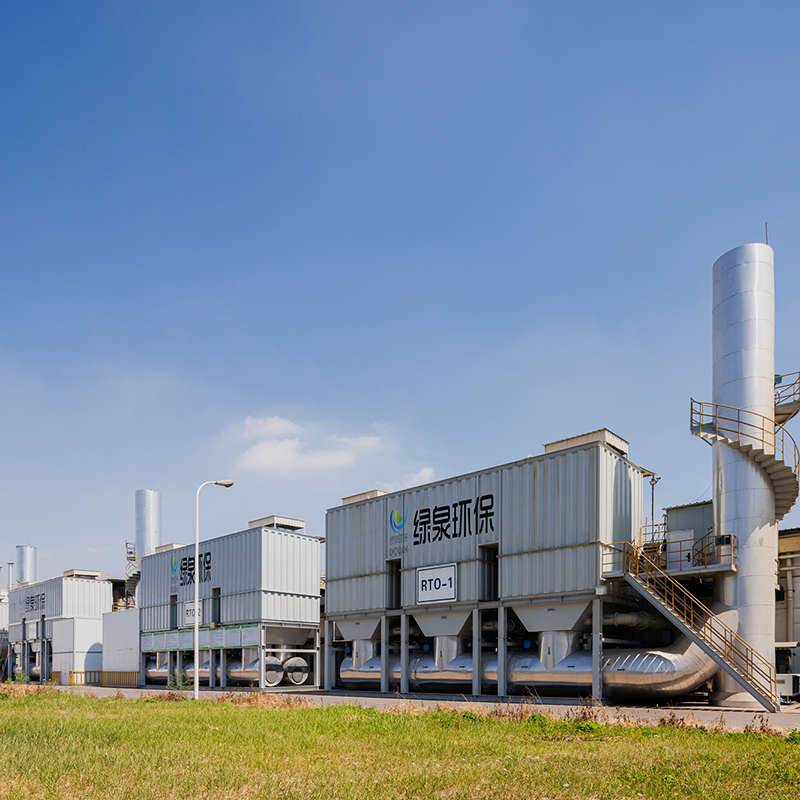
타워 형 RTO의 개요 재생 열 산화제 (RTO)는 고온 산화와 다중 타워 열 저장 기술을 결합한 유기 폐기물 가스 처리 장비입니다. 효과적으로 열 손실을 줄이고 에너지를 절약합니다.
세부 사항을 참조하십시오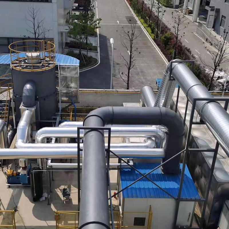
타워 형 RTO의 개요 우리 회사는 로터리 RTO와 단일 배럴 멀티 밸브 RTO 인 두 가지 유형의 로타리 RTO를 제공합니다. 로타리 에너지 저장 산화 용광로로도 알려진 로타리 RTO는 가연성 폐기물 가스를 고온에서 상응하는 산화물 및...
세부 사항을 참조하십시오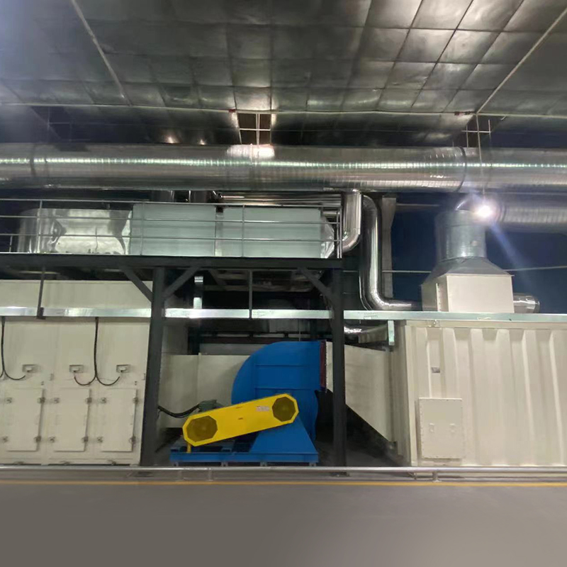
가변적 인 freouence Zeolite 턴테이블의 개요 우리 회사의 Zeolite 농도 턴테이블은 Zeolite 모듈의 조합, 높은 제올라이트 함량, 높은 흡착 속도 및 빠른 흡착 속도를 사용합니다. 그것은 독특한 기술로 처리되어 탈착 동안 더 ...
세부 사항을 참조하십시오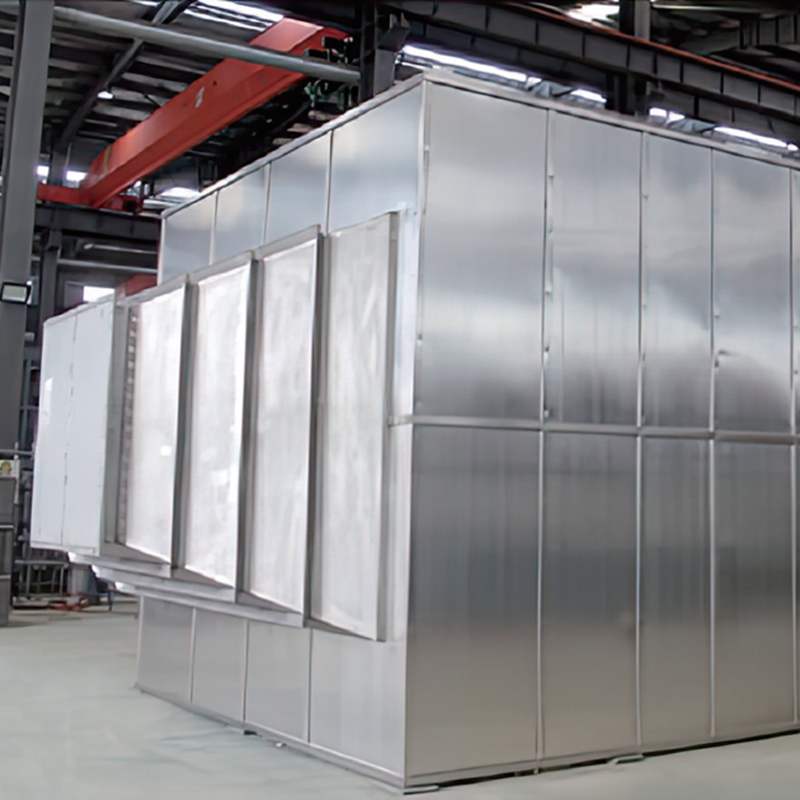
제품 소개 가스 열 교환기는 주로 다양한 산업에서 연도 가스의 폐 열 회수 및 다양한 공정 시스템에서 필요한 열 교체에서 에너지 절약 및 배출 감소 산업에 사용됩니다. 폐 열도 가스의 온도를 줄이기 위해 열 교환을 사용함으로써 열 회수 시스템은 에너...
세부 사항을 참조하십시오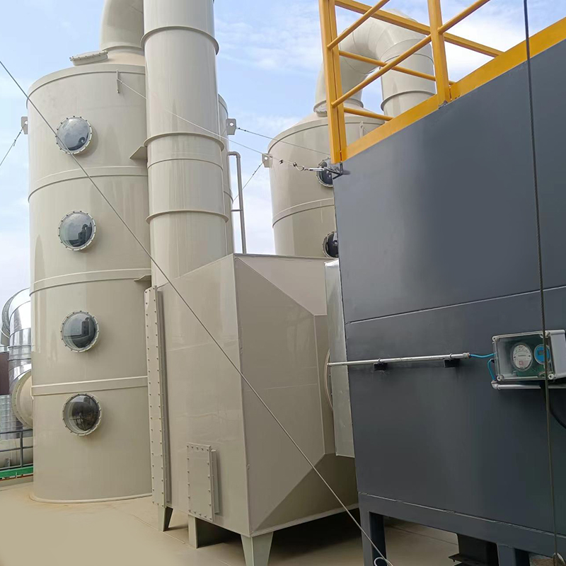
개요 VOC-ACA 시리즈 유기 가스 입자 탄소 정제 및 회복 장비는 벤젠, 알코올, 케톤, 에테르, 페놀, 가솔린 등과 같은 유기 폐기물 가스의 흡수, 회복 및 재사용에 사용됩니다.
세부 사항을 참조하십시오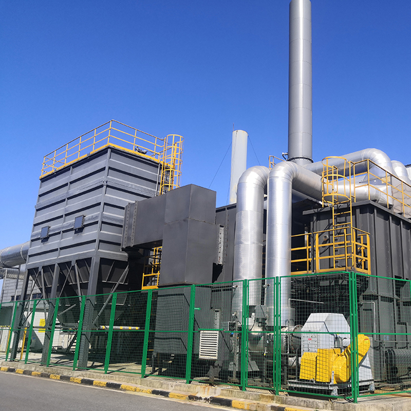
제올라이트 휠 RTO 시스템의 개념 제올라이트 휠을 사용하여 유기 폐기물 가스를 흡수하여, 저농도 및 대기량 폐기물 가스는 고농도 및 소형 공기량으로 농축되어 장비 비용 및 운영 비용을 줄이고 효율적인 VOC 처리를 달성합니다. RTO는 고온 가스 ...
세부 사항을 참조하십시오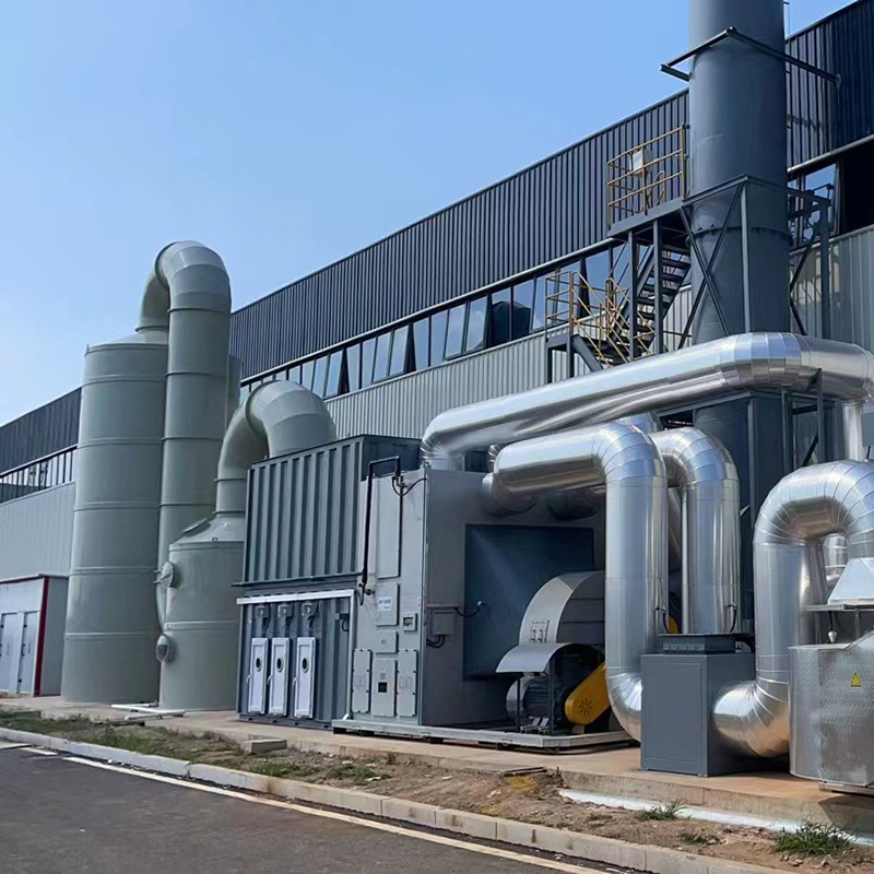
장비 세트로서 고정 침대 제올라이트 촉매 연소의 개념 고정 베드 제올라이트 촉매 연소 장치는 저농도의 농도 및 흡착 처리, 간헐적 생산 (예 : 조선 산업) 및 UV 페인트 및 스티렌과 같은 휘발성 유기 화합물에 적합합니다. 연속 안정 작동, 처리 ...
세부 사항을 참조하십시오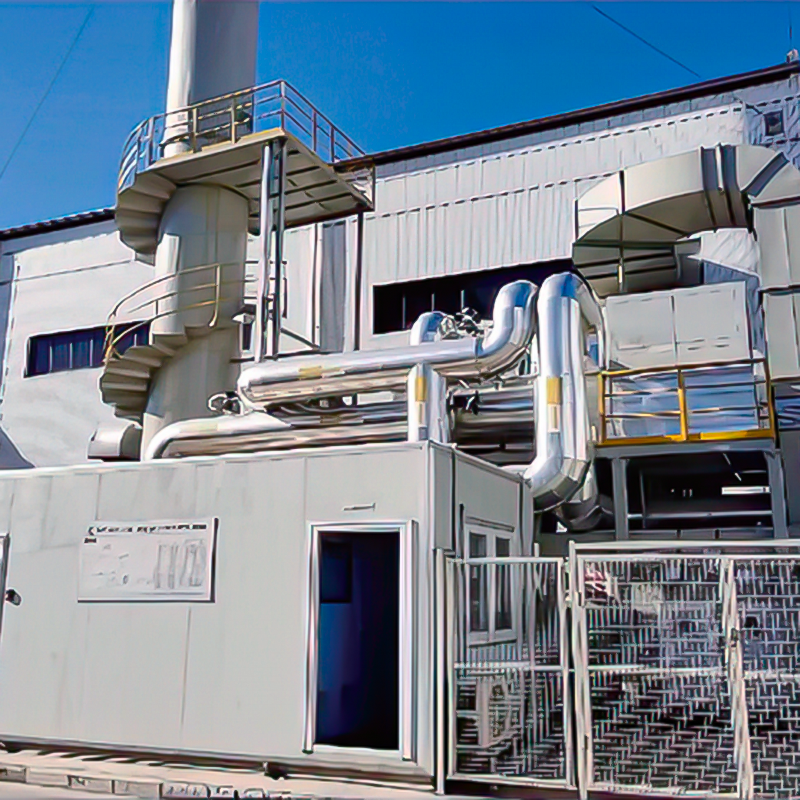
장비 세트로서 제올라이트 로터리 휠 촉매 연소의 개념 유기 폐기물 및 폐기물 가스 처리의 결합 된 공정에서, 제올라이트 로터리 휠 농도 흡착 촉매 연소 장치는 주로 공기 부피가 높고 농도가 낮은 폐기물 가스의 처리에 주로 적합하다. 그 구성 요소에...
세부 사항을 참조하십시오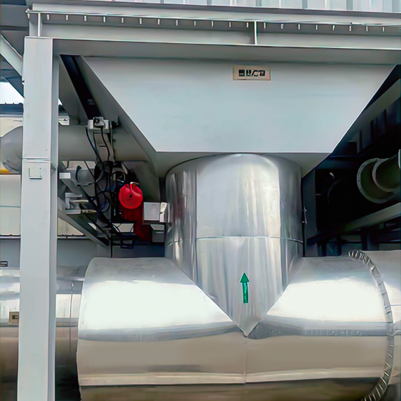
목적 주로 고온 연도 가스의 비례 환기에 사용됩니다. LT는 RTO 및 기타 고온 연기 직접 방전 장소와 같이 누출 속도 요구 사항이 높지 않은 곳에서 널리 사용됩니다. 주로 버터 플라이 밸브 본체와 일치하는 공압 액추에이터 (GT/RT/AT/AW ...
세부 사항을 참조하십시오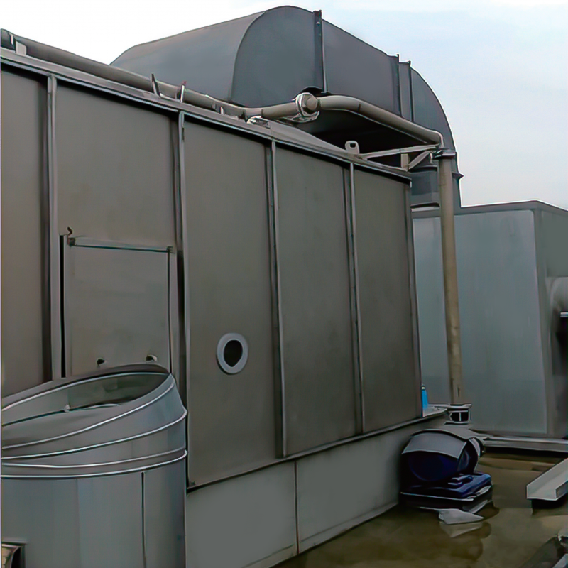
개요 습식 먼지 제거 원리는 가스-액체 2 상을 완전히 접촉함으로써 가스 상에서 먼지 입자를 포획하고 분리하는 과정을 사용합니다. 현재 일반적으로 사용되는 구조적 형태는 다음과 같습니다. 1. 물 저장 : 일정량의 물이 설치되고...
세부 사항을 참조하십시오이동하는


Copyright © LV Quan 환경 보호 엔지니어링 기술 Co., Ltd. All Rights Reserved. 유기농 폐기물 가스 처리 공학 장비 제조업체

